Find and Characterize Cracks in Concrete

DAnoBi (Detection of Anomalies in Image Data)

The universal building material concrete is strong and resistant, but brittle. Thin cracks in concrete are almost unavoidable, but usually not harmful either. For the inspection, diagnosis and maintenance of concrete surfaces, cracks must nevertheless be reliably found and evaluated. Experts often assess crack patterns purely visually.

Concrete and crack structures vary greatly depending on the field of application. Concrete surfaces can be very irregular. It is therefore difficult to reliably segment thin crack structures automatically.

We have developed two very flexible and robust solutions for this task – one using classical image processing and one using machine learning (ML). They find hairline cracks that are only one pixel thick even on heterogeneous backgrounds.

In Focus 3D Images and Computed Tomography

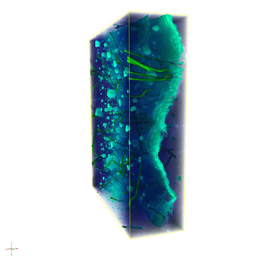
Cracks in the interior can be imaged non-destructively using computed tomography. However, they usually appear only slightly darker in the 3D images than their often very heterogeneous surroundings. Finding cracks reliably, recording their course completely and analyzing them is therefore particularly challenging in 3D.

In the DAnoBi project (Detection of Anomalies in Image Data), we are working with partners to develop methods that can find and segment cracks even in images as large as 400GB.

The Future: Globally Unique CT System for the Construction Industry

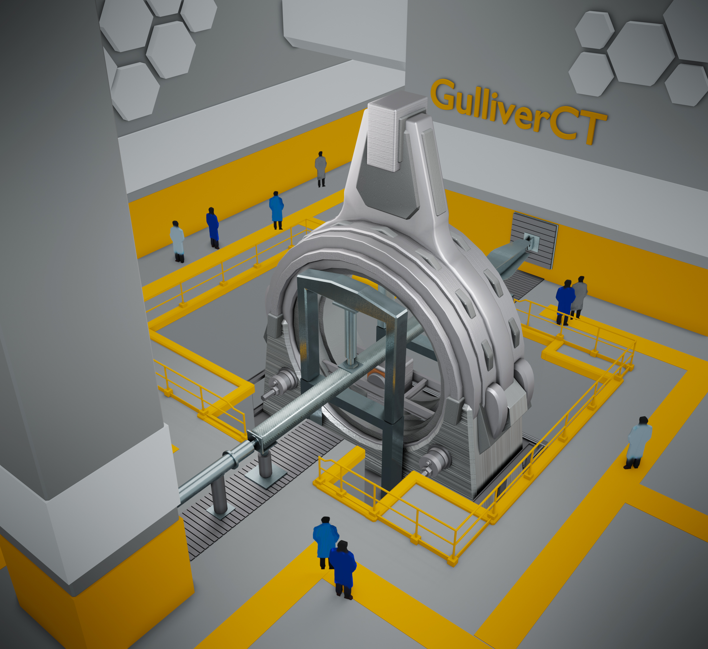
A great challenge: Micro-CT technology like the one we use at Fraunhofer ITWM scans concrete specimens with edge lengths and diameters of only a few centimeters. Mechanical load tests on concrete specimens several meters long cannot be performed. In the future, this will be possible at the Rheinland-Pfälzische Technische Universität Kaiserslautern-Landau (RPTU), in the Department of Civil Engineering. A globally unique CT facility is currently being built there, which will go into operation in the summer of 2023. The facility works with much stronger X-rays – nine megaelectronvolts – than medical X-ray machines, so that reinforced concrete components up to a diameter of 30 centimeters and a length of six meters can be X-rayed.

Computed tomography portal Gulliver.
© Fraunhofer ITWM
Computed tomography portal Gulliver.
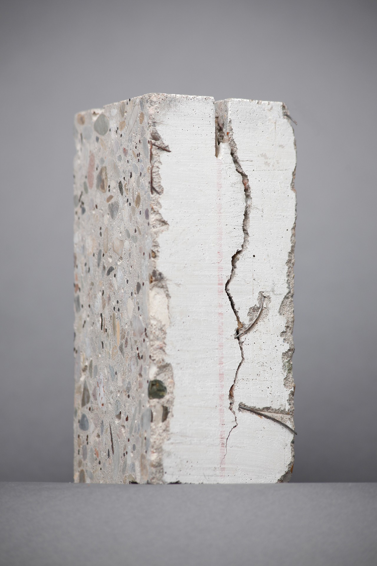
Concrete sample with crack.
© Fraunhofer ITWM
Concrete sample with a crack.


One of the first and most important application scenarios in Gulliver, as the large-scale device is called, is the 3D imaging of crack development in large concrete beams during a four-point bending test. The three-dimensional X-ray images of these processes are very informative for research. The technique will help scientists better understand concrete, a complex composite material. For each experiment, Gulliver generates between 120 gigabytes and two terabytes of image data. The goal of the research is 3D imaging and analysis of the structural changes caused by the bending load during the ongoing experiment.

More about Gulliver, the CT system (large-scale equipment initiative) of the RPTU Kaiserslautern-Landau (German Website) 


Our Expertise and Scope of the Project

At Fraunhofer ITWM, we are optimizing the memory management and image evaluation of our extensive 3D image processing and analysis software in order to be able to deal efficiently with the huge amounts of data generated. The complex algorithms must allow for short response times in image processing. This is a demanding task, since it is necessary to find the finest structures in the huge amount of data within a short time. For this purpose, the ITWM software offers extensive analysis methods, for example for local porosity, thickness, and orientation analysis.

The plan is to combine the expertise of civil engineers with 3D image analysis in order to optimally select and parameterize complex algorithms, correctly evaluate intermediate results and correct errors as early as possible. To this end, an AI assistant is being developed that learns the expected workflow and data flow, as well as expected intermediate results and typical error patterns. Among other things, it is trained on the basis of CT measurement parameters and sample properties – such as dimensions and material mix – in order to evaluate the image data quality. This ultimately provides civil engineers with a better basis for calculating the load-bearing behavior of concrete components, for example, and as a result they can save material and optimally adjust the proportion of reinforcing steel or fiber required.

In the future, quantum computing will also accelerate the analysis of CT data.

More About Quantum Computing at Fraunhofer ITWM

Visualization in CT Image in 3D Image.
© Fraunhofer ITWM
Visualization in CT Image in 3D Image.
2D: Concrete slab with cracks.
© Fraunhofer ITWM
2D: Concrete slab with cracks.
2D: Cracks in concrete slabs
© Fraunhofer ITWM
2D: Cracks in concrete slabs.